Week 3 (June 13th-19th)
Mechanical
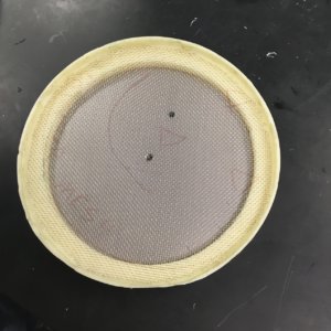
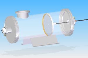
Collector finished
At the very beginning of week 3, we measured the dimensions of the chamber again to determine a more precise requirement for the collector plate. According to the requirements, that there should be enough gap between the plate and the chamber and that the mesh need to be ensured insulated to the chamber, we made some adjustment on the design of the collector plate. A 175 mm diameter metal plate was used tom replace the original 190 mm diameter plate. The plastic plate was redesigned and processed to be suitable for the new metal plate. And a plastic edge was used to insulate the mesh and the chamber. After three days of learning, trying and overcoming different difficulties, we used the drilling machine and finished the manufacture of the collector plate. The only thing missed for this part is a matching screw to fasten the metal plate, the plastic plate and the Teflon rod together.
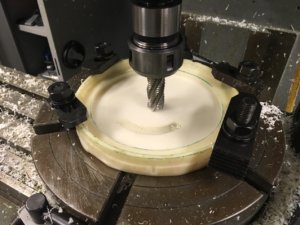
Collector isolation plastic being finalized in the mill
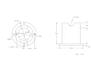
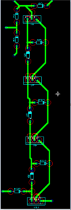
Creo 3D Model used to get accurate dimension to build the injector
Moreover, based on the requirements of the experiment, we redesigned the injector and re-determined the dimensions of the parts of it. As a high precision of process is desired, we used Creo to develop 3-D models of the injector so that a high quality manufacture is possible. Also, with great effort, we finally acquired the permission of using the CNC machine, which is under the charge of the Mechanical Eng
ineering Technology department. It means that the components of the injectors can be processed with high efficiency and satisfactory quality. Hopefully, the injector will be finished in next week. By then, every major parts of the experiment equipment would be finished. And we can assemble them together and test the equipment. If everything goes smoothly, we are optimistic to get the experiments started in two weeks.
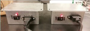
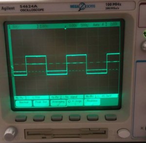
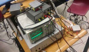
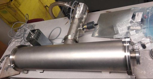
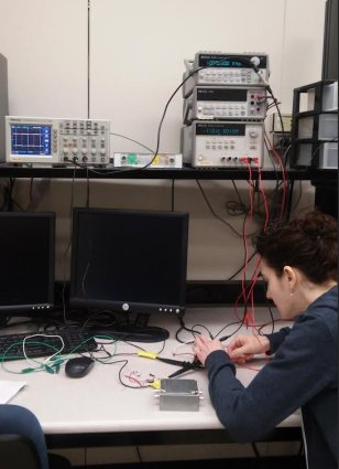
In addition, since the pulse generator, oscilloscope, function generator and the high voltage supply are already set up, we set up our work space for future experiment.
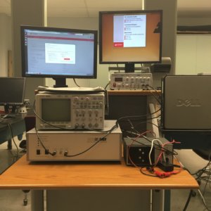
Experimental Setup
In a conclusion, we achieved satisfying progress in week 3. Things are getting ready for the fully commence of the experiment.
Electrical
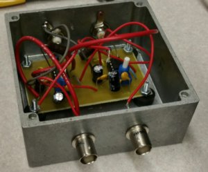
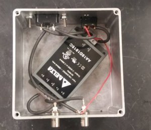
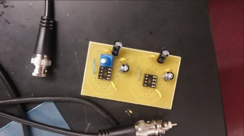
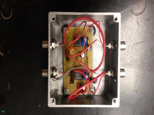
Electrometer tested inside box
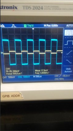
For week 3, the first iteration of the electrometer was successfully tested and completed: we used an oscilloscope to test the gain for each amplifier stage which led us to the discovery of a faulty operational-amplifier. After replacing the faulty op-amp with a new one and obtaining the desired gain, we added the 220KΩ resistor to the first stage, tested again, and confirmed the desired gain result. Next we finalized the electrometer by trimming excess wire on the board’s underside and drilling 4 holes (one per corner) in which to screw on small rubber “feet” so that the board may stand evenly and securely inside the metal housing apparatus.
Next we hooked up our oscilloscope and computer for data acquisition and analysis: our particular oscilloscope/software requires an RS-232-C connection. We had a DB9 Serial RS-232 cable with two male ends, but our PC port was also male (see images below for detail) so we obtained the proper adapter and hooked it up accordingly.
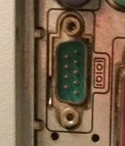
RS-232 Male Port on PC
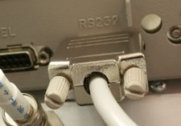
RS-232 connection to Oscilloscope

Both RS-232 were male
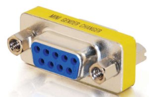
The adapter we purchased
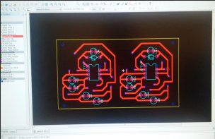
Lastly, we designed another circuit using transistors to implement our high-voltage power supply. Below are the circuit diagram and the schematic created for the circuit board using Ultiboard software.
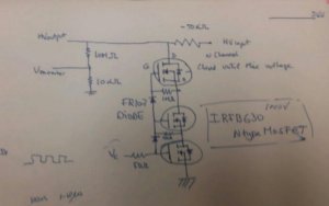
HV Switch using MOSFETS
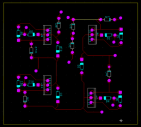
Switch Schematic. Ready to print
For the coming week (week 4) we will continue building and begin subsequent testing of this circuit, as well as begin coding for data acquisition / analysis.