
MURI Project: On the way to the Stars
This is the blog where we show our Progress towards building a Time of Flight (ToF) chamber to measure the properties of Ion Beams for Electrical Propulsion.
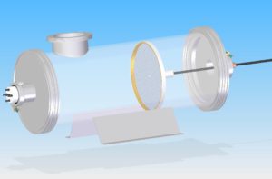
CAD Design of the ToF Chamber
Week 1 (June 1st-5th 2016)
Agenda:
• Set up
• Equipment Test
• Trial Run
• Understanding
This was an interesting week for the team. It began with the team meeting on Wednesday June 01st, followed by regular lab work.
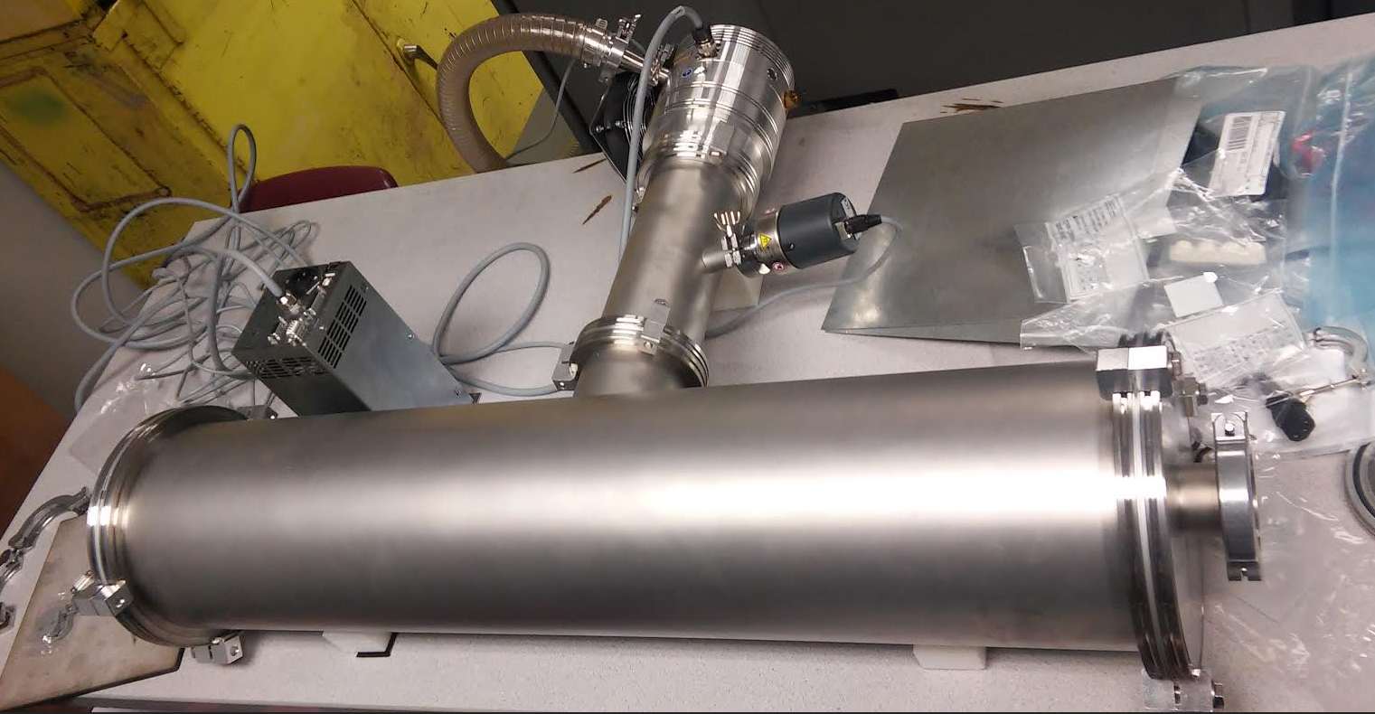
Time of Flight Chamber. Turbo and mechanical pump attached!
In our first meeting we were able to complete obtaining the dimensions for the diameter of the plastic casing of the collector. We were also able to acquire the dimensions of the collector plate, keeping in mind the angular spread of the electron beam and separation from the chamber itself. Rest of the chamber assembly went smoothly without many hurdles. The only problem we ran into was with a missing connector part to connect the primary vacuum to the secondary one.
By Thursday, our second lab session, the PCB boards were designed and our primary vacuum was connected for testing purposes. We ran into a problem when we were unable to connect our vacuum to a power supply due to its high voltage requirements and the transformer wouldn’t take that much load.
Friday was a great day! We were able to connect the missing part and have a complete test run of the chamber and vacuums. The PCB was printed by evening and we were able to understand the working of the remote control for use with the secondary pump. We were able to reach a low pressure of around 1.2E-07. We also were able to have the electrometer presentation prepared.
Week 2 (June 6th-12th 2016)
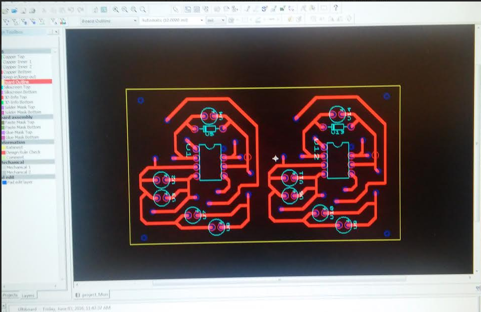
Two stage electrometer circuit design
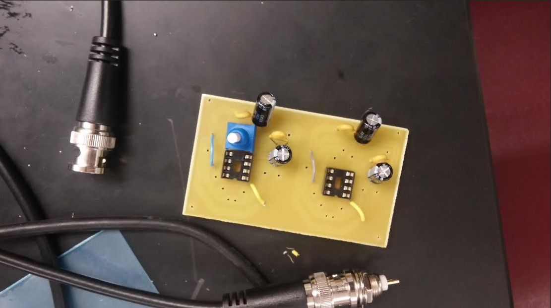
Circuit Board Printed. Let us add the components
The electrometer was built in order to measure electrical potential at extremely low values without drawing any current from the circuit. In order to make the electrometer, a layout was needed to be placed on a printed circuit board. We used Ultiboard to design the circuit diagram as shown above.
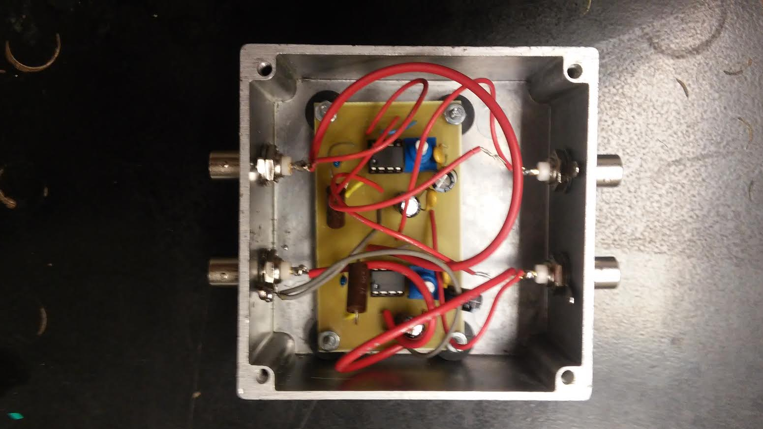
Electrometer assembled and put into the box. Ready to test it!
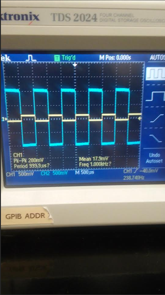
The printed circuit board was then printed out and the parts were then assembled onto the board. Once done, we tested the gain using an oscilloscope. The results were expected as the first stage of the electrometer had a gain of -10 and both stages together had a gain of 100. Once the desired results were obtained, the electrometer was then connected to the BNC connectors
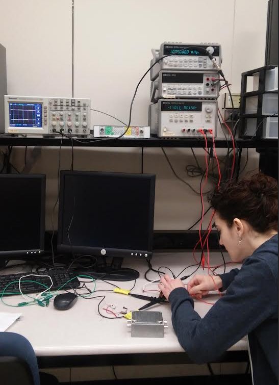
Bree is testing the electrometer and making sure that everything is properly working.
It works!!
