
Week 4 (June 20th-26th)
Mechanical
Electrical
This week we built 2 power supply boxes that each contained an AC-DC power module, an AC wall outlet, a switch, an LED (to signify switch “ON”) and outputs. One box provides the required +15V / -15V to the electrometer and the other box provides the required -15V to the collector. The images below show a box under construction, and the two completed boxes together:
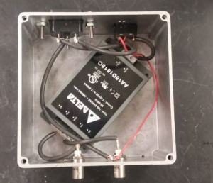
Power supply for Electrometer.
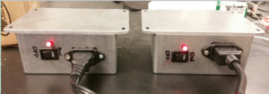
Two power supplies are ready
After constructing the boxes, we hooked up the electrometer’s box to verify that everything is working correctly, and indeed everything worked as expected. We will test the other box for the collector when the collector is ready. Below is an image of the electrometer outputting the desired waveform when tested with its power supply box:
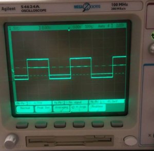
Oscilloscope reading signal from Electrometer
We also built another box for the High Voltage (HV) power supply (see image below, bottom right) which houses all of the live and grounding wires that connect the HV supply to other including the high voltage pulsar and the DC power supply.
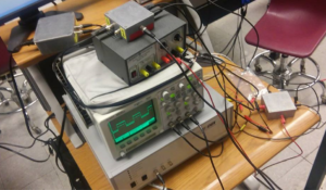
Oscilloscope, electrometer setup
The circuit board of the HV supply we’re building with transistors was also redesigned (see image below) to improve reliability and ease of use as the original had the potential to create a short and had unnecessary components.
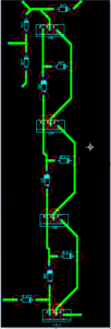
Switch diagram redesigned
